 HOME
HOME





In the not-too-distant future, provided the manufacturers can cross the certification finish line, we may see eVTOL aircraft flying around our cities and towns. To ensure the safety of 3rd parties, the certification of these new machines will need to consider what happens if something fails on the aircraft. Helicopter certification accounts for the failure of a critical engine and the flight profiles required to manage such failures during take-off and landing. What can eVTOL designers and operators learn from helicopters in the certification of profiles to deal with failures?
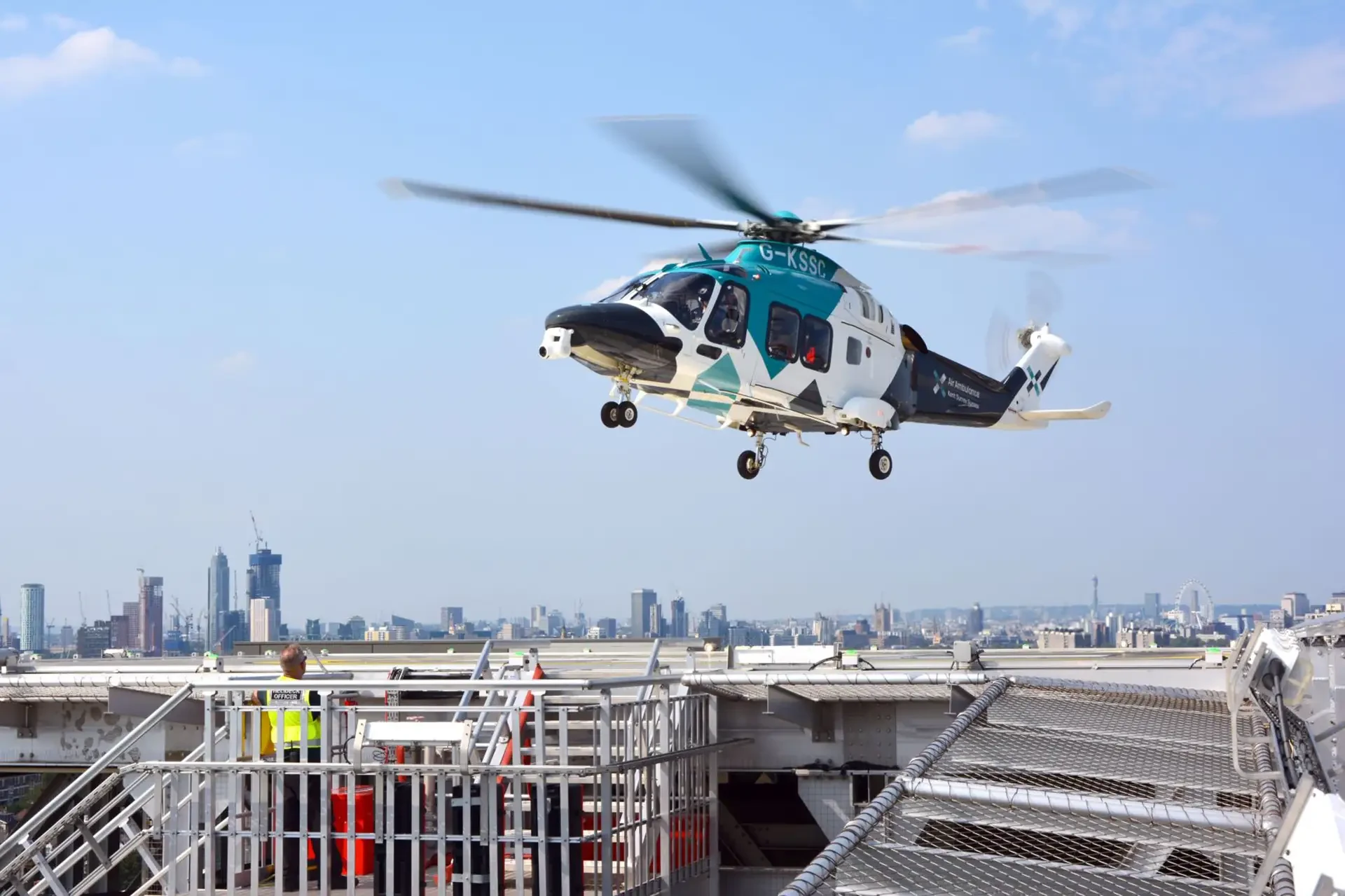
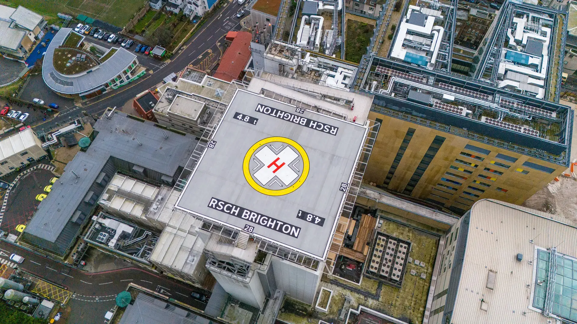
Category A profiles are a necessity to safely operate in Performance Class 1 to elevated helipads
Background
This requirement to consider failures is an embedded part of the certification process for helicopters and is captured in the Certification Specifications (CS - CS-27 for <3175 kg or CS-29 > 3175 kg). Currently, for helicopters, the main focus for ensuring the safety of the aircraft has been the loss of a critical power unit, a single engine failure. This is a hangover from a fixed-wing view of what is a critical failure, and this needs a rethink for many-engined eVTOL.
eVTOL Certification
For eVTOL, the CS do not exist yet, so EASA has published a set of Special Conditions (SC - SC-VTOL) which are progressively being updated
as knowledge of eVTOL grows. eVTOLs typically have distributed propulsion systems, and SC-VTOL requires that other critical failures be
considered, including a power unit failure. This might include loss of a propeller or rotor, while the tolerance for a bird strike is now
also a baseline requirement. We will pass over the probabilities involved in failure design for the sake of brevity.
In addition, because there are so many power units, the reliability target for each individual unit can be set at a lower level. An aircraft with 30 engines can give a 'gallic shrug' at one unit dropping offline, so why bother making the power units super reliable? In this situation, the failure case the designer actually might have to consider is multiple failures of less reliable engines (for example, 3 of 30).
Category Enhanced
To demonstrate tolerance of a critical engine failure during certification, helicopters can be certified as Category A. This includes design features and performance information to assure adequate designated surface area and adequate performance for continued safe flight or safe rejected take-off/landing in the event of engine failure. In simple terms, anything else is Category B but there are still a lot of requirements for the design of such a helicopter.
For SC-VTOL, it is 'Category Enhanced' for an aircraft that can continue flight or complete a safe landing following a critical failure. It is then 'Category Basic' for an eVTOL that is not certified to Category Enhanced, but again, there are still a lot of design requirements at this level.
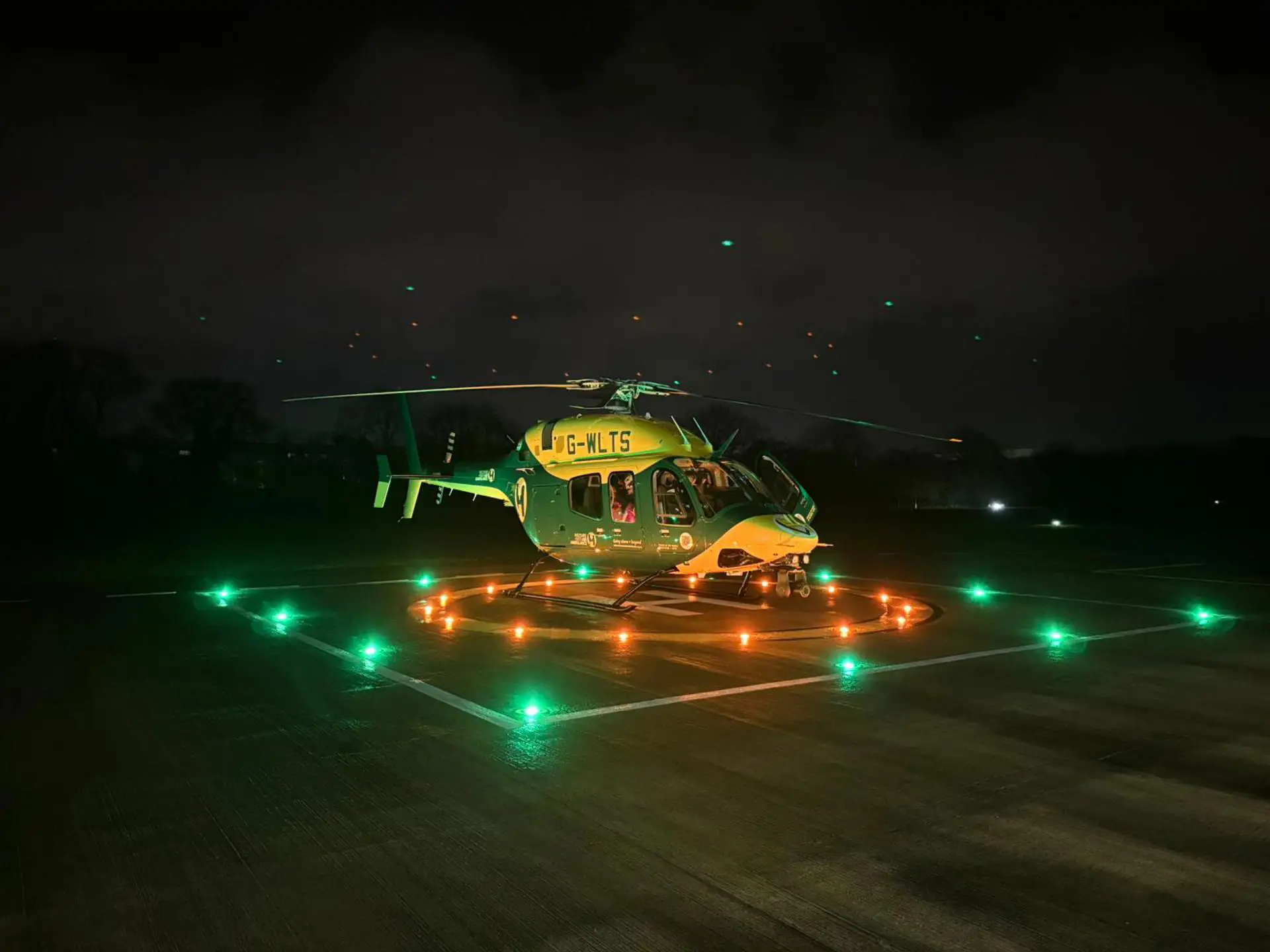
As part of Category A and Category Enhanced, there must be appropriate profiles for the pilot to follow during the take-off and landing phases so that the pilot can guide the aircraft to a safe continued flight or a safe landing in the event of a failure. Typically, for a Category A helicopter, there will be a clear area profile and a helipad profile as a minimum, with additional profiles added to enhance the aircraft's capability. For example, the AW109 and EC135 have short field profiles to operate to short, prepared strips. Many helicopters also have deck approach profiles for offshore work and confined area profiles for operating into sites surrounded by obstacles.
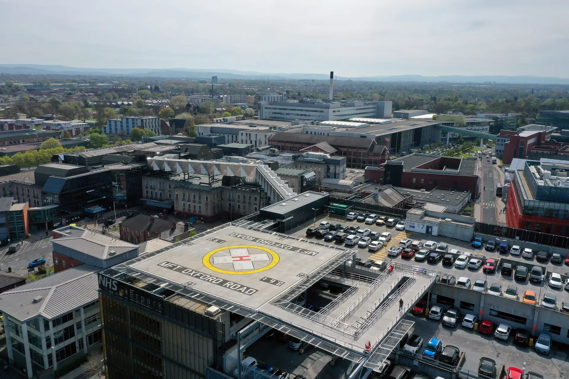
Hospital landing sites present a rich obstacle environment that helicopters have to safely traverse using Category A profiles
As it stands, there is minimal guidance on SC-VTOL profiles, and as such, a clean slate exists for eVTOL designers. Helicopter Category A profiles have evolved over time, building on lessons learned and technological improvements. What lessons should eVTOL take from this long evolutionary process for application to Category Enhanced profiles? We are going to focus on light twin turbines here because they are closest to the current crop of eVTOL in terms of weight class.
Evolution of Helicopter Category A Profiles
The first practical light twin turbine helicopter was the Bo 105, certified by LBA in 1970. It was closely followed by other aircraft like the A109 and S76. In developing early procedures to address single-engine failures, there was a natural tendency to follow fixed-wing best practices without fully exploiting what a helicopter could do. First, some core foundations of the topic.
Basic Category A Principles
Energy
The core requirement for Category A profiles is to provide appropriate, safe options in the event of losing the critical power unit. The aircraft must maintain sufficient energy at all times to either land safely or execute a missed approach. The two major ways of maintaining that energy are height (potential energy) or speed (kinetic energy). With insufficient amounts of these combined, the aircraft could crash during the go-around or hit the ground hard during a reject. Therefore, our Category A profile needs to provide a path that maintains the aircraft's energy level at an adequate level throughout.
Vision
Another important requirement is that the pilot can actually see what they are trying to land on. Thus, visual conditions must exist, and the landing profile typically keeps the landing point within the pilot's natural field of view. A true vertical landing profile from height is now seemingly impossible as the pilot's view would be blocked by the fuselage (hold that thought - we will come back to this later).
Mediocrity
We cannot design our helicopter or procedures just for exceptionally good pilots. Most of us need to be average for the exceptional to exist! The capability of an average pilot to consistently fly the helicopter through any Category A profile must be assured. Making our take-off or approach profile too difficult to follow would lead to excessive variation in achieved performance.
Early Category A Profiles
Clear Area/Runway
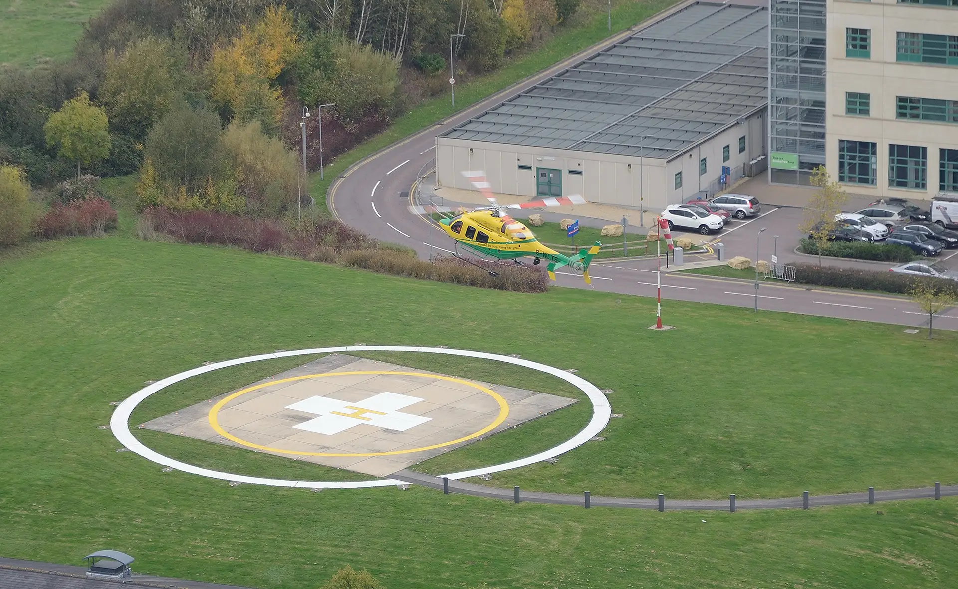
The starting point for Category A profiles is the fixed-wing world and how they manage performance to and from a runway. In a controlled airfield environment, helicopters can afford to conform with fixed-wing norms, so the landing profile can be an extremely simple straight-in approach with a "gate" at a set height and speed. The height and speed are determined to leave the committal point (Landing Decision Point - LDP) to the last possible moment, where a safe go-around can be completed by Captain Average. The landing point is kept in sight throughout. above the instrument console.
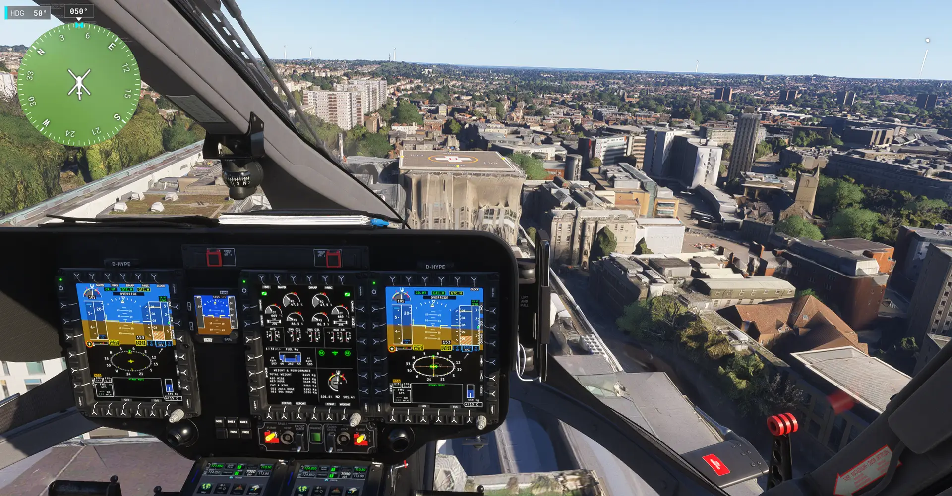
A clear area Category A approach profile - HPG H145 / Microsoft Flight Simulator 2024
For take-off, a normal helicopter forward transition can be used, targeting another "gate". Where manufacturers looked to make the required runway as short as possible, the manoeuvre could get a little "sporty". The AW109 normal clear area category A take-off is a great example of this. From the hover, pull a lot of power and push the cyclic to fill the windscreen with a plan view of the surface. A 25o, nose-down attitude change at 3ft above ground is exciting! Not great for the passenger's Gin and Tonic, though, and hence a "soft" version was created with a longer runway requirement.
In any case, VTOL will probably need something similar, but there is not much scope for innovation; the profiles used on helicopters for a clear area have barely evolved since the 1970s.
With the helipad approach and departure, there is a lot more scope for creativity.
Helipad
The simplest way to create a profile for a safe landing on a helipad is to mirror the clear-area profile we have already looked at. The profile keeps the landing point above the instrument console, but it is therefore shallow. Despite actually coming into service in the 1990s, the MD902 serves as an example of this simplistic approach profile. The RFM specifies an LDP of 100 ft with the picture from the cockpit for a "...6 degree sight picture..." This gives a distance from the landing point of around 290m for a 10.5% slope.
It's easy to fly, and we can keep the speed up at 35kt at LDP, so what's the problem? The main issue is the large area of real estate that must be free of obstacles under the approach path, as the approach is so flat. Unhelpfully, the MD902 Flight Manual also provides no information on which obstacles are permitted.
In urban environments, the only ways to achieve this clear space would be to place an elevated pad above the rest of the obstacles or to put the landing site away from buildings. This constrains the operation of the helicopter, making it far less useful.
The Bell 212, certified back in 1972, actually had better numbers in this respect, with a 200ft LDP at 275 m out from the helipad for a 22% slope. Still, a large, relatively obstacle-free area is needed under the shallow approach.
We need to get smarter with our profiles if this is going to be useful for an eVTOL.
Category A evolves - getting steeper
If we want to get our helicopter down amongst the obstacles with a progressively smaller obstacle-controlled area, we have to get our approach and take-off steeper. As we have already mentioned, a pure vertical profile blocks our view, so we need to think laterally, literally. A feature of many helicopter instrument consoles is that they dip down around the edges, and/or there is a gap between the console and the side of the cockpit. We can achieve a shallower gradient while still keeping the landing site in view by shifting the visual picture to put the landing site to the side of the instrument console.
This approach was used on early BK117 and EC135. The right "sight picture" put the landing point somewhere off to the side of the instrument panel. For an EC135, this achieves an LDP of 120 ft at 80 m back from the pad for a 45.7% gradient. Now we are getting somewhere. We can tolerate some obstacles around our landing site. However, our missed approach path still takes us straight towards our landing point, necessitating a path clear of obstacles on the other side of the pad as well. Our view of the landing sites is starting to get obscured by aircraft structure if we make even small errors.
Due to the flexibility of a helicopter, there are methods to improve the view. On the BK117 B2, the numbers are pretty similar, with 140 ft LDP at 80 m back from the pad. However, the poor view of the landing site due to the instrument console was improved by yawing the aircraft 15-20° to the left to keep the site in view. However, it was still a mediocre view at best!
Our gradient is getting steeper, so we can tolerate higher obstacles closer around the site. But is there a way we can go even steeper?
Even steeper - using the chin window
Our obstacle environment is still quite constrained. Where else can we keep the landing site in view from the pilot's seat? The chin window!
On the EC135T3 and AW169, the Category A helipad profile puts the landing site view between the pilot's ankles. This gives a 61% gradient for the EC135T3 and a 99% gradient for the AW169. However, we are now comprising the simplicity of the procedure. At night to a poorly lit site, these approaches and take offs can be quite challenging. A little yaw or an error in descent gradient can put the lights of the landing area out of view.
H135 view of landing site between feet - HPG H145 / Microsoft Flight Simulator 2024
Unless we put a window in the floor, this is about as steep as we can go with a straight-in approach. The controlled obstacle area close to the landing site has been reduced in size, making urban landings more practical.
But have we really explored all the options? Could there be something in that yaw the BK117 B2 used to keep the site in view?
The side window - a diagonal approach
In many helicopters, the side view is better than straight ahead due to the absence of the instrument console and the deep side windows. Why don't we put the landing site in this sector of the pilot's view to allow an even steeper approach?
This is exactly the strategy adopted by Bell on the Bell 429. The landing site is located just above the lower handle on the pilot's side door. The aircraft can either be yawed 45° to achieve a straight-in approach or flown offset from the direct line to the pad, with a diagonal transition onto the pad from LDP.
Bell 429 view of landing site using H145 surrogate - HPG H145 / Microsoft Flight Simulator 2024
From a practical perspective, this should increase the steepness over the AW169 we saw earlier. We are now looking right down the side of the helicopter from the pilot's seat, and it feels quite vertical. However, if you look at the published numbers in the RFM, it's only a 89% gradient. By observation from the outside, it’s probably more like 150%!
Can we go even steeper?
We now have a very steep approach profile, which minimises the area around the landing site where we need to keep the obstacles low. We can offset the approach path to the side and diagonally approach the landing site once alongside. This is actually the basis for some rig offshore approaches, such as the VTOL 4 on H135.
Can we take this offset style of approach to another level by making it a true sideways approach?
Thinking laterally - going sideways
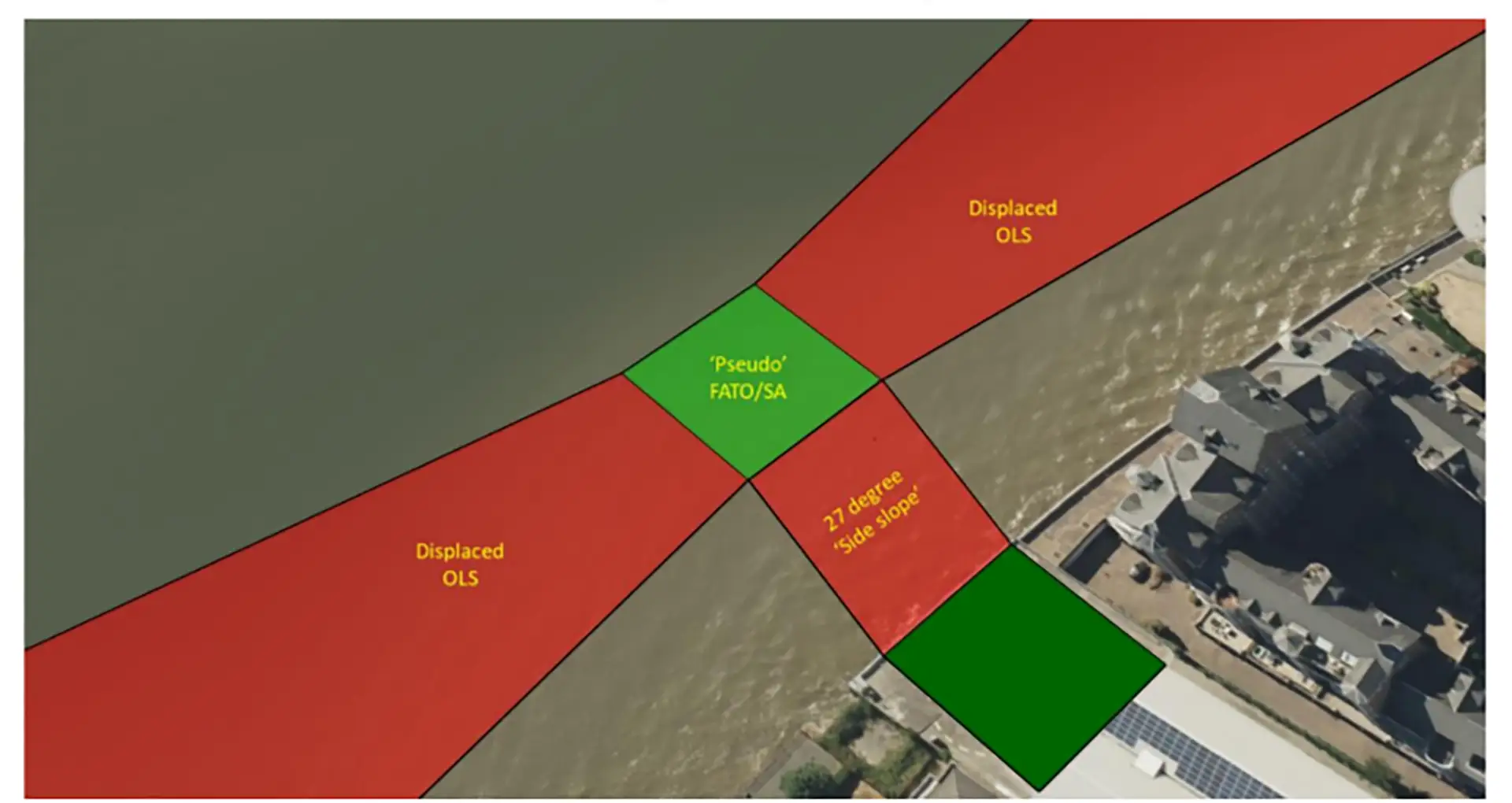
The flexibility of the helicopter allows for a sideways approach. This concept is captured in a future update to ICAO Doc 9261 - Heliport Manual and has been applied to some constrained landing sites along rivers.
Possible method for creating obstacle limiting surfaces for an offset approach path - ICAO
An approach is made offset from the landing site to an area relatively free of obstacles (such as a river). The approach is made to a pseudo-FATO where the aircraft has sufficient energy/height for a go-around. However, once committed, the aircraft slides sideways onto the helipad, possibly using the yawing motion we already mentioned to improve the view of the landing site. This profile is particularly useful for sites on riverbanks or coastlines where a direct approach is too difficult. It does rely on an adjacent clear path, so it may not be useful in some circumstances.
Skyports Heliport - Google Earth
We now reached a zenith of steep approaches using the humble eyeball. Could technology go the next step?
Video cameras for the vertical
A pure vertical departure is relatively simple to achieve with a modern Automatic Flight Control System (AFCS). Get airborne over your helipad, engage hover mode on the AFCS, and climb slowly with the collective. In the event of an engine failure, control rate of descent with collective, leaving the hover hold engaged to ensure the aircraft does not drift.
But landing is a different ball game. How is the aircraft safely established directly above the helipad in a free air hover when you cannot look straight down? And even if you could look straight down, this would be an uncomfortable seating position (ask any long-liner pilot).
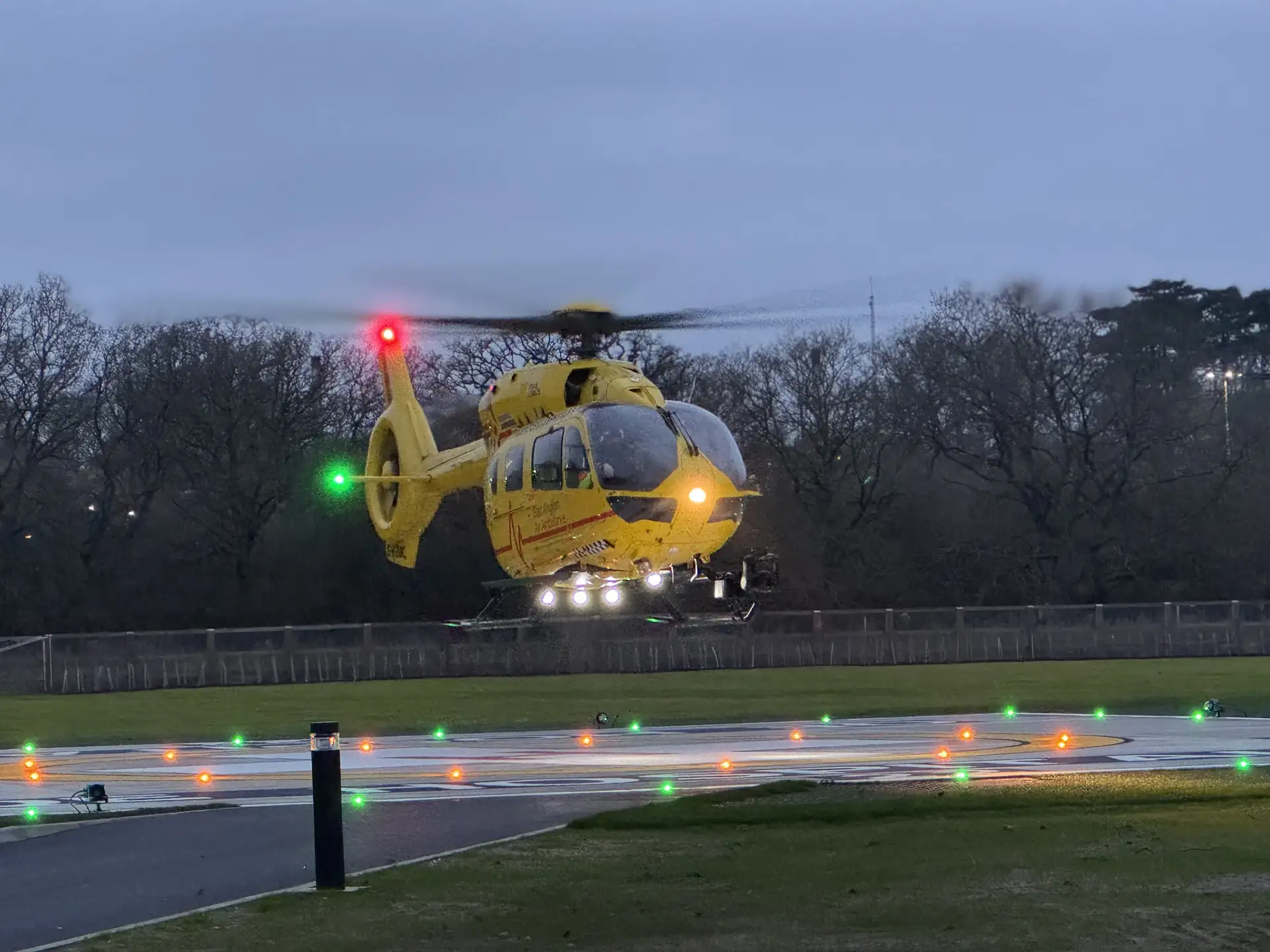
The solution is to use 100-year-old technology, a trusty video camera. Mount a carefully angled video camera under the tail, and you can see exactly what is underneath the aircraft. Add some modern computer wizardry to project an aiming reticule to the exact point directly below the aircraft, and we have a safe means of reaching the correct free-air hover point over our helipad. From there, we just need to engage our hover mode again and control the rate of descent with collective.
We have now achieved the absolute smallest possible obstacle-constrained area for our helipad. A landing site can now be surrounded by obstacles on all sides. Provided the obstacles can tolerate the downwash and the aircraft has sufficient performance, we can operate to almost any clear space that is large enough. Newer aircraft have protections and warnings to prevent the vortex ring condition, enabling safe vertical flight. Have we reached the pinnacle of Category A profile design, and is it an exemplar for Category Enhanced to follow?
Well, nearly.
More resilience needed
Remember the tolerance of failure principles for Category Enhanced? Should the camera fail, the lens become contaminated, or the hover AFCS mode fail, we would be unable to make the true vertical approach. We might have to abandon our approach for a minor issue like a 'bug strike' on the camera.
This is a possibility covered in the vertical approach profiles, which already exist; for example, on the Airbus Helicopters H145 D3. The crew is reminded that the profile is unavailable should the hover mode or camera be unserviceable. The crew needs a backup plan. This will likely require a steep, visually judged approach. Such a reversionary procedure must be part of any eVTOL design strategy and operational plan.
The impressive native hover mode on H145 should be the model for VTOL looking to do vertical departures - HPG H145 - Microsoft Flight Simulator 2024
Conclusions
The increasing trend towards helicopters using true vertical arrivals and departures at confined heliports is definitely something eVTOL designs should 'bake in' from the start. Modern helicopters will need to have the capability natively going forward if they are to compete with existing designs. But having a steep, visually judged Category Enhanced profile will be necessary to ensure continued operation in the face of inevitable system mishaps.